Why Many VFD Retrofits Underperform Without a Controls Recalibration Plan
Share

Variable-frequency drives can stabilize airflow, reduce fan energy use and smooth out system operation, but many retrofits fall short of expectations because the supporting controls never get updated.
The drive is installed, the fan modulates and the rest of the system continues behaving as if it still has a constant-speed blower. When controls remain calibrated for fixed airflow, efficiency, comfort and reliability all suffer.
Where VFD Retrofits Typically Fall Short
Most underperforming VFD projects share the same root cause: the original sequences were never rewritten for variable airflow.
Systems that once relied on full-speed operation now require updated logic for pressure, airflow and equipment staging. Without that recalibration, the drive ends up reacting to control signals that were never designed to modulate.
Common mismatches include static pressure targets set for constant-speed blowers and airflow assumptions baked into economizer logic. Morning warm-up cycles and purge routines can become unstable because their timing and temperature targets were tuned for maximum airflow rather than variable operation.
Legacy Logic Working Against New Drive Behavior
Older AHUs, RTUs and makeup air units were designed around predictable airflow. When a drive modulates, the rest of the system may misinterpret normal fan turndown as a fault condition.
Unchanged control sequences often lead to rapid modulation, short cycling at low demand and airflow-related nuisance alarms.
Problems usually trace back to logic written for equipment that only had two positions: on and off. Drives introduce a continuous range between those points, and without updated sequencing, the controls fight the modulation rather than working with it.
Sensor Placement and Calibration Problems
A VFD depends on accurate data. Once airflow becomes variable, sensors that worked adequately at a constant speed can produce unstable readings. Poor sensor placement around elbows, transitions or turbulent airflow creates noise that drives erratic fan behavior. Field issues often involve:
- Static pressure sensors mounted too close to supply fans
- Return sensors drifting after years of operation
- Temperature sensors positioned where turndown creates short-circuiting or stratification
When inputs are unreliable, the drive hunts, overshoots and fails to maintain stable pressure or airflow.
Mechanical Realities That Controls Must Reflect
A recalibration plan has to address mechanical constraints, not just programming. Many systems have airflow characteristics that limit how far a VFD can turn down without compromising performance. Key mechanical boundaries include:
- Duct systems that develop unstable pressure at low speeds
- Return limitations that prevent adequate airflow during turndown
- Equipment that loses coil performance below a minimum CFM
- Supply air temperature swings that appear when modulation exceeds the unit’s range
A successful integration plan calibrates the drive to operate within what the ductwork, coil and fan assembly can reliably support.
Common Signs a Retrofit Lacks Controls Integration
Underperforming VFD projects tend to show the same symptoms across midsize commercial buildings:
- Fan speed never dropping to designed minimum airflow
- Duct pressure oscillating around setpoint
- Economizers failing to reach full open due to outdated airflow assumptions
- Low-airflow safeties tripping despite adequate capacity
- Higher energy use than expected because the drive is fighting fixed sequences
These issues often persist until the control logic is rewritten to match the drive’s capabilities.
What a Controls Recalibration Plan Should Include
A complete plan goes beyond the drive installation and addresses how the system will operate in real conditions. Essential steps include:
1. Redefining minimum and maximum airflow for equipment protection and comfort
2. Updating static pressure control loops to support modulation
3. Recalibrating or relocating sensors to deliver stable readings
4. Revising economizer sequences, warm-up routines and purge cycles
5. Validating performance at multiple fan speeds and load conditions
Commissioning That Protects the ROI of a VFD Retrofit Project
Commissioning after a VFD retrofit ensures the system performs as intended rather than as assumed. This includes functional tests for each operating mode, documenting acceptable pressure and temperature ranges and confirming that staging and economizer strategies behave consistently at modulating airflow.
Trending helps verify long-term stability so facilities teams know what normal operation should look like.
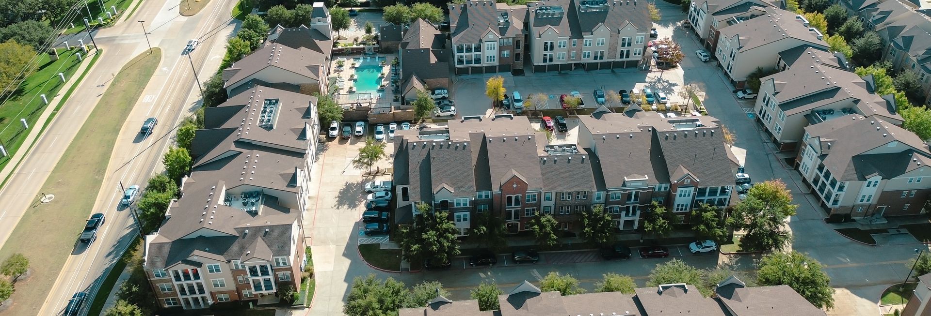
Why System-Level Integration Matters for Facilities in Arlington and Fort Worth
Without recalibrated controls, the expected gains from a VFD retrofit rarely materialize. If a recent VFD retrofit isn’t delivering expected savings, coordinate a controls assessment with Tom’s Commercial by calling 817-857-7400. Or bring our DFW commercial HVAC experts into the evaluation phase to verify system compatibility before retrofitting.